|
|
The mechanical
object that I chose to model and animate is an air-cooled engine. More specifically
the engine is designed and manufactured by Volkswagen. The size of the engine
is 1700cc. It has four cylinders that are mounted horizontally. The engine
is from a 1972 Volkswagen Transporter, commonly called a Type II. The main
moving parts are the camshaft and crankshaft. The crankshaft is what drives
the camshaft by a spur gear as shown in the picture below.
|
|
|
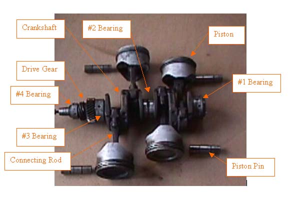
| The crankshaft
has 4 bearings that are attached to it. The connecting rods are then attached
to the crankshaft. There are four connecting rods, since the engine has
four cylinders. The Pistons are attached to the connecting rods by means
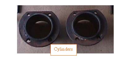
of a pin. As the crankshaft rotates it will move the piston back and forth
inside the cylinders. Below is a picture of them. (There actually are four
of them, since there are four cylinders). |
|
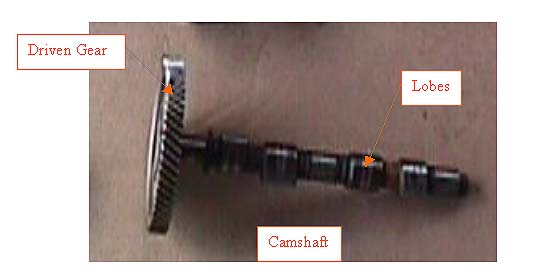
| The camshaft
while being driven by the crankshaft actually pushes a follower through
its bore. The part of the camshaft that actually does the pushing is the
lobes. The picture below is of the camshaft: |
|
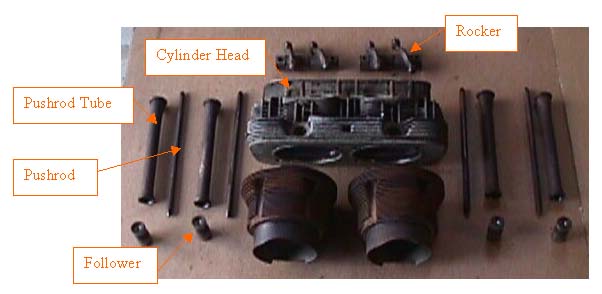
| The followers
will then move the push rod through the push rod tube. The push rod rocks
the rocker back and forth. The rocker compresses the valve springs, which
in turn pushes the intake and exhaust valves through the bore in the cylinder
head. The picture below shows these components. |
|
| The final
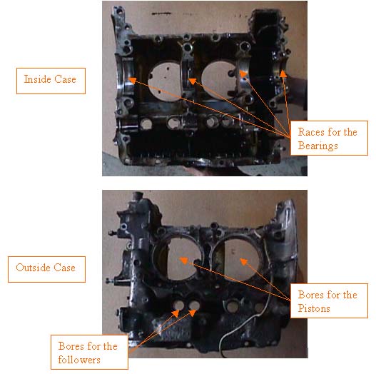
component in the assembly is the engine case. The engine case is actually
in two halves. The engine holds the bearings, camshaft, and crankshaft and
engine oil. The pictures below show one half of the case inside and outside.: |
|
| The
operation of this air-cooled engine is quite simple. The compression of
the engine occurs between the valves and the piston. Combustion will occur
when there is fuel and a spark to ignite the fuel. The movement of these
parts needs to be timed correctly in order for compression to occur at the
right time. This is timed by the lobes on the camshaft and by the journals
on the crankshaft. Each cylinder has two valves, one for intake and one
for exhaust. The rocker has two pivots that will push each of these valves. |
|
Parts
List
|
| Name |
Qty |
Name |
Qty |
| Crankshaft |
1 |
Cylinder Heads |
2 |
| Camshaft |
1 |
Rockers |
4 |
| Connecting
Rods |
4 |
Followers |
4 |
| Pistons & Pins |
4 |
Valves |
4 |
| Bearings |
4 |
Valve Springs |
4 |
| Engine Case |
1 |
Push Rods |
4 |
| Cylinders |
4 |
Push Rod Tubes |
4 |
The
nuts and bolts that hold most of the parts together were not added to
the parts list for simplicity reasons.
|
|
Back
to the Project list
|
