|
Introduction to
AutoCAD
Learning Outcome:
By the end of this module, the learner will be able to:
- Navigate the AutoCAD interface
- Use AutoCAD Help
- Enter Commands
- Start new drawings
- Perform basic File commands (New, Open, Save)
- Enter and use basic draw commands
- Use basic display navigation tools
AutoCAD Interface
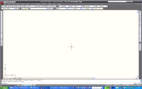
*Note: AutoCAD 2009 contains multiple user
interfaces, notably a new MS Office-styled 'ribbon' interface (below,
left), and a classic interface (below, right), each with its own
advantages and disadvantages. Your instructor will determine which
interface is most appropriate for your classroom use.
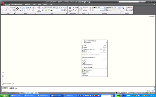
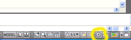
The interfaces can be switched by accessing the
Workspace tool.
|
FUNCTIONS OF AUTOCAD'S INTERFACE
|
| Pull Down Menu |
The Pull Down Menu is one
way to access all of AutoCAD's Functions and commands.
The pull down menus are organized into logical
categories. Some pull down menus have sub menus. |
| Standard Toolbar |
The Standard Toolbar
contains all of the standard windows typical commands
such as file commands, printing, undo and redo etc... |
| Objects
Properties Toolbar |
The Object Properties Toolbar
controls all aspects of an AutoCAD Objects properties
such as colour, linetype, lineweight etc... |
| Docked/Floating
Toolbars |
Toolbars
may be Docked (attached to the edge of the
screen) or Floating (in the middle of the
screen). Most AutoCAD commands are accessible through
these toolbars. To un-dock a toolbar simply drag it by
its top to a location in the center of the screen. To
prevent a toolbar from docking while positioning it hold
<ctrl>. Toolbars may also be resized by dragging an edge
or corner. |
| Scroll Bars |
Scroll bars at the edges
of the screen can be used to reposition the page (up,
down, left or right) |
| UCS Icon |
The UCS (user coordinate
system) icon acts as a guide to point in the positive X
and Y directions in your drawing. A 'W' within this icon
denotes that you are working in the world coordinate
system. |
| Command Prompt
Area |
The Command Prompt Area is
for typing. All AutoCAD commands are accessible by
typing. Either the full name of the command is typed or
if available a command short-cut or alias can be used.
(the line command is LINE with an alias of L) |
| Coordinate
Readout |
The Coordinate Readout is
where you can see the current location in the coordinate
system your curser is currently located. This area
doubles as a Tooltip Readout. If you place your
curser over a button a one line description appears here
stating what the button is used for. |
| Status Bar |
The Status Bar shows which
drawing tools are active at any given time. A button in
this bar pressed in is active. A raised button is
inactive. |
| Drawing Area |
The Drawing Area is where
you will do your actual drawing. This Black area
stretches on in all directions infinately. |
|
Using AutoCAD's Help
Function:
- To access the Help command:
- Type HELP at the
command Prompt
- Click on the ? Icon in
the Standard Toolbar
- Press function Key F1
- Select Help from the Pull Down Menu and
select AutoCAD Help
- Once inside the help command you will have
three choices (tabs):
- Contents - Allows you to click through to
topics in the same way you would use the Table of Contents in a
Textbook
- Index - Allows you to search by name for a
topic or command.
- Search - Searches the entire AutoCAD Online
help for matches to the word entered.
- Other Help Tips
- You can Bookmark Help topics for easier
reference later.
- You can print Help topics to keep in your
notes.
- Use Forward and Back buttons to navigate.
- Follow underlined words to similar commands
and more detailed examples.
- Remember Help is always there! Just look it
up!
Command Entry In
AutoCAD:
- There are several ways to enter commands in
AutoCAD; pulldown toolbars, icon selection, type the command name,
or type its command alias (shortcut).
- Rules for typed command entry:
- No Spaces in command names (AutoCAD
interprets spaces as an enter or return)
- The command must be typed correctly. (i.e.
not misspelled, AutoCAD cannot guess what you really want to do)
- Commands are NOT case sensitive.
Tips for Command Entry:
- Hitting Enter or Space will repeat the last
command entered.
- Hitting up or down arrows will cycle you
through a list of recent commands. Hit enter when the command
you want is visible.
- Right-clicking in the Command Prompt Area
will pop-up a menu, recent commands is a list of the most
recently used commands.
- Learn the short-cuts or alias for each
command to work faster.
Other Command Entry Tools
- Dynamic Input Option
- Use of Mouse - context sensitive menus
- Graphics Window versus Text Window- Use of F2
- UCS Icon and related Coordinate Display
- Opening and switching between Multiple Drawing
- Running Multiple Copies of AutoCAD - NOT RECOMMENDED
File Commands:
NEW
- To create a NEW file:
- Type NEW at the Command
Prompt
- Click on the button marked with a blank page
in the Standard toolbar.
- Or use the File Pull-down and click on New
- When starting a New file the default
setting for AutoCAD is to select a template file, which provides
settings for the file type, most importantly units setup. ISO
templates are metric, others are imperial.
SAVE & SAVEAS
- To SAVE your drawing file:
- Type SAVE
- Click on the button with the Disk in the
Standard Toolbar.
- Or use the File pull-down and click on Save
- To Save your drawing file as a new name:
- Type SAVEAS
- Or use the File pull-down and
click on SAVEAS
- When you save your file you will need to
give it a NAME and a LOCATION.
- The drawing NAME can be
anything you like but avoid special characters like ! @ % ^ & *
( ) etc... keep it to letters and numbers.
- Your drawing file will be
saved with the file extension .DWG
- There is no limit to the
length of the name you give your drawing, BUT if you
which to work with older versions of AutoCAD limit your name to
eight characters.
- The same rules apply when creating and naming
the location of your file.
-
REMEMBER what
you named and where you saved your file. A lost file is just as
bad as a deleted or unsaved file.
-
SAVE OFTEN.
Computer and user error could cause you to crash. Save your
drawing every 15 min to avoid lost work.
-
BACK-UP your
drawings. Copy your drawings onto storage devices and store them
in a safe place so that should anything go wrong you have a
back-up copy. This is your insurance policy against disaster.
Starting Drawings from Scratch
- Measurement system
- Units
- View - Zoom - All
OPEN
- To OPEN your drawing:
- Type OPEN at the
Command Prompt.
- Click on the button with the Open Folder in
the Standard Toolbar.
- Or use the File pull-down and click on Open.
- When Opening your file you will
need to REMEMBER what you called it and where you saved it.
- Look at the right of the OPEN
dialogue to se a preview of your drawing as it was when you saved it
last.
BACK-UP FILES
- AutoCAD can create automatic
back-up files of your drawings, BUT do not rely on them!
- Back-up files are created after you save your
drawing for a second time.
- Back-up drawings have the file
extension .BAK
- To Open a Back-up file use
Windows explorer to rename the file. Change the .BAK
extension to .DWG
Work Strategy
- Always open files from a local fixed drive (i.e. DO NOT work directly
from removable media or a network drive)
- Back-up you important data files to a safe location (O: drive!)
Basic Draw
Commands
AutoCAD Drawings are made up of basic
elements or objects. We will use these basic objects to create our
drawings. Some of the basic object types are:
LINE [ L
]- The line command creates a line defined by two points which the user
selects by either clicking those points or typing coordinates at the
command prompt.
CIRCLE [ C
] - The circle command draws a circle defined by its center and
radius/diameter, or 2 or 3 points on its diameter.
ARC [ A ]
- The arc command creates an arc which is defined by three pieces
of information such as center, diameter/radius, arc length, angle, and
direction. Arcs are usually drawn counter-clockwise.
Please note: To execute these commands
either type them at the command prompt, use the draw pull-down, or click
on the appropriate button.
Understanding the Screen Display
- Zoom
- All
- Extents
- Window
- Previous
- Pan
- Redraw/Regen
- Using the mouse to pan and zoom
|