
|
| Faculty of Applied Science and Technology |
| School of Architectural Technology |
| ARCH 17991 ARCHITECTURAL DETAILING: Residential |
|
Module #6 -
Controlling Sound Transmission |
||||||
|
Learning Outcomes: |
Glossary: Airtight, Heavy, Limp Partitions
|
|||||
Supplemental Readings: |
Text Reference: Chapter 5 Controlling Sound, pp.73
|
|||||
| Controlling
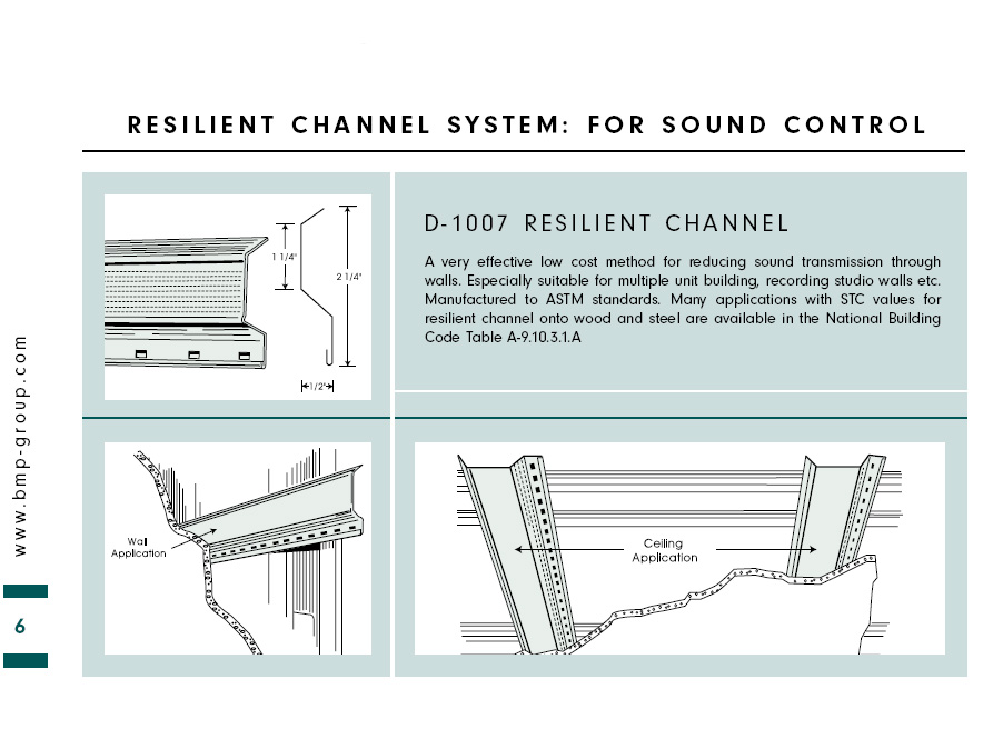
Sound Controlling sound (specifically noise, or undesirable sound) is an important aspect of Architectural design, as it affects both human comfort and life safety. Mechanical systems should be detailed to minimize the creation and transmission of noise. Structural system should have connections that do not make noise. Spatial separations should be detailed to reduce sound transmission and maintain privacy, especially separations between public and private zones. Rooms intended for regular use by occupants should provide good acoustic conditions that facilitate human interaction. To fulfill these requirements, we can use the following detailing strategies: - Airtight, Heavy, Limp Partitions (pg
74) The ability of an assembly to resist the transmission of sound is measured in decibels. These values are reported as an STC rating. For recommended ratings see the table on page 68. For STC ratings for various partition types refer to Fig. 5-1 & 5-2 page 74. |
||||||
 |
||||||
| The metal wall and ceiling framing shown above is from the Bailey Metal Products website visit it and get this information and more | ||||||
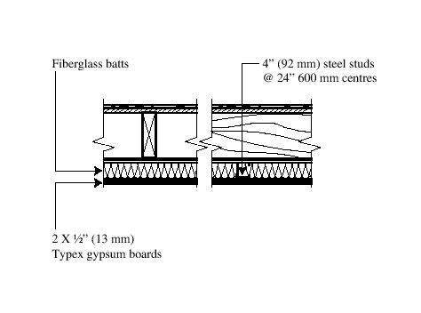
| How to improve the soundproofing of an existing floor Many duplexes or triplexes built between 1900 and 1950 have wood floors which, with few exceptions, are similar to the one illustrated in Figure 1 below: This type of floor attenuates airborne sound and readings vary between STC 45 when the floor is bare and STC 50 when it is covered with a carpet. As for impact noise insulation, the reading varies between IIC 40 and IIC 70. The latter is achieved when a high quality carpet is installed over a thick rug underlay that covers the entire surface of the floor. A CMHC-initiated study conducted in the early 1980s (CNRC publication DBR 1147), an acoustic separation of STC 45 between two units resulted in an occupant dissatisfaction rate of 25%.The easiest and most effective way of improving the sound insulation of an existing floor/ceiling assembly illustrated in Figure 1 below, involves an additional ceiling consisting of two 13-mm X type gypsum boards screwed to standard 25-gauge metal studs 63.5-mm (2 ½) or preferably 3 5/8 (92-mm) deep, which are screwed directly on and perpendicular to the joists of the existing floor at 16 or 24 (400 or 600-mm) centres. The 600-mm (24) centres are preferable from an acoustic viewpoint. Glass fibre batts are placed in the cavity between the metal studs before installing the gypsum panels on the ceiling. The joints of the ceiling gypsum boards should overlap by at least 300 mm (12). The joints of the first level of gypsum boards need not be taped. The recommended changes are illustrated in Figure 2 below. According to a study done for CMHC in 19881, since there are no flanking channels, it is reasonable to expect an STC of 55 and an IIC of 50 (without wall-to-wall carpeting) when the new ceiling is installed.
|
||||||
|
|
||||||
