
AutoCAD - Enhancing Drawing Accuracy
Note: Classic view screenshots used in this module are taken from AutoCAD 2000i, whose interface closely reflects the AutoCAD 2009 'Classic' interface.
RULE NO 1 - NEVER, EVER, "EYEBALL" THE LOCATION OR LENGTH OF A LINE (OR OTHER AUTOCAD ENTITY). ACCURACY IS A MUST!!! ALWAYS!
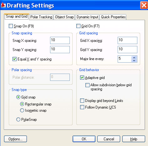
Using the Grid and Snap commands in combination enhances the accuracy of your drawings by "constraining" the cursor within a standardized grid system. Note the following;
|
Classic View Samples
 |
Access the Drafting Settings through the Tools Menu or by right-clicking one of the icons. | AutoCAD 2009
Samples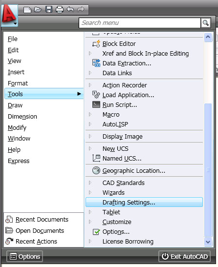 |
 |
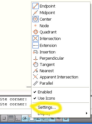
Alternatively, Right-Click over the Grid or Snap button on the Status Bar, then Choose Settings . . . |
 |
 |
Change the Grid and Snap setting then OK. |
 |
 |
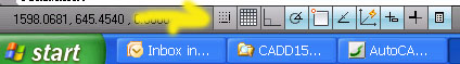
Switch Grid and Snap ON/OFF using the buttons on the Status Bar |
 |
Drawing accuracy is greatly enhanced through the ability to attach a line (or other entity) onto an existing point in a drawing, such as the end point of a line. This is known as object snapping (Osnap).
When prompted to provide a point, do one of the following
 |
Use the keyboard/mouse combination of Shift+Right-Click to bring up the Osnap Menu OR |
 |
Pick the Osnap setting from the Object Snap Toolbar |
| Common Object Snap Settings | |
 |
To snap onto the end point of a line or other entity |
 |
To snap onto the mid point of a line or other entity |
 |
To snap onto the intersection point where two entities cross |
 |
To snap onto the centre point of a circle or arc |
 |
To snap onto aquadrant point of a circle |
 |
To connect a line perpendicular to another line |
Running object snapping programs AutoCAD to ALWAYS look for particular snap settings whenever it is looking for a point. Running object snaping can be switched ON/OFF. Note the following;
- The Running Object Snap settings needs to be setup before it will work properly.
- The Running Object Snap system need to be switched ON to activate it (Use the buttons on the Status Bar).
| Running Object Snap | |
|
|
Access the Drafting Settings through the Tools Menu |
 |
Alternatively, Right-Click over the OSNAP button on the Status Bar, then Choose Settings . . . |
 |
Check-off the Osnap modes you wish to program AutoCAD to look for. |
 |
Switch Osnap ON/OFF using the buttons on the Status Bar |
Polar tracking constrain (snap to) the exact angle that lines will be drawn when they are close to a given angle. Note the following;
| Polar Settings | |
|
|
Access the Polar Settings through the Tools Menu |
 |
Alternatively, Right-Click over the POLAR button on the Status Bar, then Choose Settings . . . |
 |
Set the angle to constrain linework. Note if 30 is chosen, lines will be constrained for the following angles; 0, 30, 60, 90, 120, 150,180, 210, 240, 270, 300, 330, 360. |
 |
Switch Polar Tracking ON/OFF using the buttons on the Status Bar |
When used in conjunction with Polar Tracking, Direct Distance Entry (DDE) is a quick and accurate method for drafting. Note the following;
The absolute coordinate system requires input of coordinates as they relate to the origin or 0,0. The coordinate is made up of two values. (There actually is a third value - the z component - but in 2D drafting it is always zero)
| Drawing the Triangle using Absolute Coordinates | ||
| Task | Command Line Prompt: | You type: |
| Start line command | Command: | LINE |
| Start the line at point A | Start Point: | 2,1 |
| Draw line from A to B | Next Point: | 6,1 |
| Draw line from B to C | Next Point: | 6,4 |
| Draw line from C to A | Next Point: | 2,1 |
| End the command | Next Point: | ENTER |
The relative coordinate system requires input of the change in direction of x, and the change of direction of y from the point you are currently at. There is a special character used to distinguish this coordinate from the absolute coordinate system. That symbol is the @ character. (i.e. @ delta-x, delta-y or @3,0 to move 3 in the x and zero in the y).

Drawing the Triangle using Relative Coordinates Task Command Line Prompt: You type: Start line command Command: LINE Start the line at point A Start Point: 2,1 Draw line from A to B Next Point: @4,0 Draw line from B to C Next Point: @0,3 Draw line from C to A Next Point: @-4,-3 End the command Next Point: ENTER
The
relative polar coordinate system borrows the @ symbol from the relative coordinate
system but uses a vector to determine the next point to use. This vector is
specified by a distance and an angle.
Drawing the Triangle using Relative Polar Coordinates Task Command Line Prompt: You type: Start line command Command: LINE Start the line at point A Start Point: 2,1 Draw line from A to B Next Point: @4<0 Draw line from B to C Next Point: @3<90 Draw line from C to A Next Point: @5<216.87 End the command Next Point: ENTER
Copyright Sheridan College Institute of Technology and Advanced Learning 2008