Sheridan College
Architectural Technology
ARCH29969 - STUDIO 3
MODULE 10: STRUCTURES: THEORY AND SYSTEM DESIGN
By the end of this Module, students will:
TABLE OF CONTENTS
1.0 Load-Bearing Capacity
2.0 Lateral Stability
3.0 Standards and Nomenclature
4.0 Steel Super-structure Framing
5.0 Concrete Framing Systems (containing class project information)
6.0 Architectural Coordination
7.0 Foundations (containing class project information)
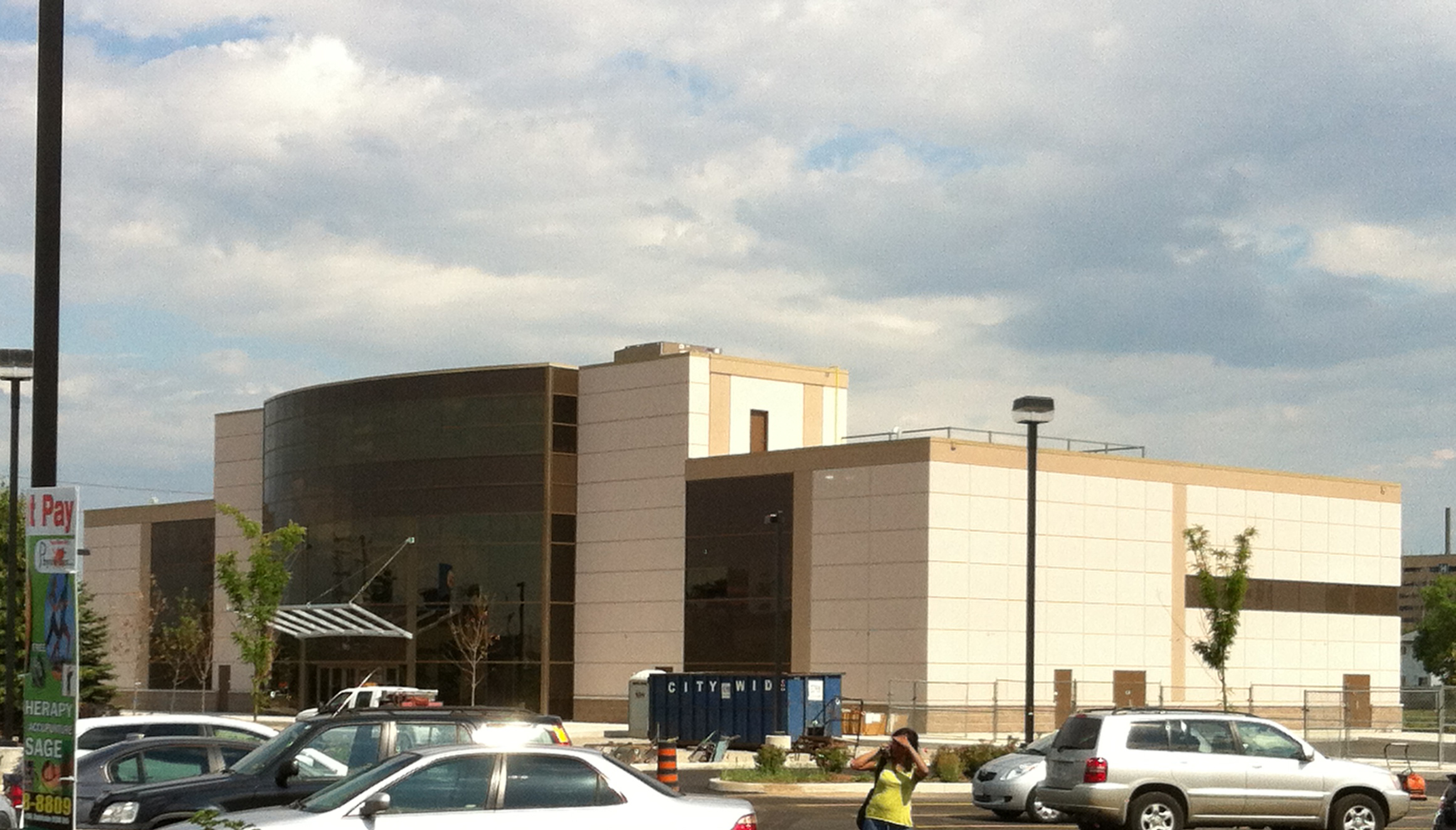
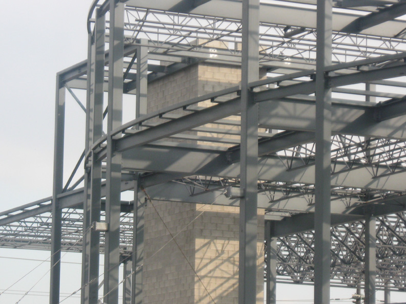
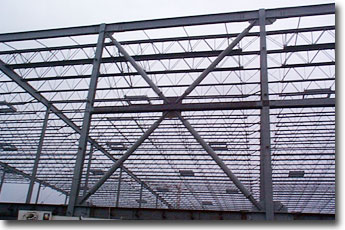
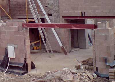
Photos to discuss: finished building is above, the following PDF shows the steel structure inside.
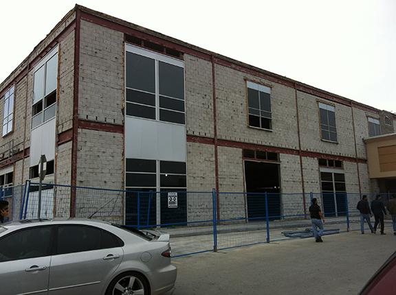
Photos to discuss: finished building from first example, close-ups of lateral framing. Photo above is a local renovated building, additional photos of the shear wall framing here.
3.0 Standards and Nomenclature
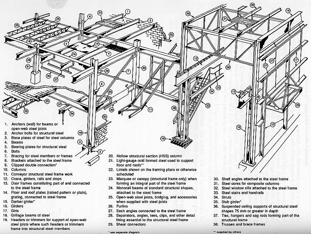
Review these diagrams. At the least, the diagram below summarizes our structural system that we could use for our class projects:
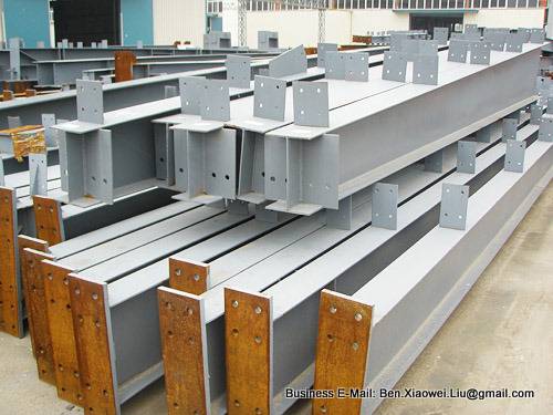
4.0 Steel Super-structure Framing
Before you embark on sizing your structural framing system, an understanding of a particular term is necessary:
TRIBUTORY AREA
We must know what this means in order to understand how structural calculations work, and tie this to the theory of structure in general.
4.1 Design Criteria
All the links below are taken from "The Architect's Studio Companion". Design Criteria for the Selection of Structural Systems should be your first step:
A Summary Chart of relevant systems:
The subsequent pages are the various charts to read based on your building data:
4.2 Span Ranges
4.3 Steel Beams and Open-web Steel Joists (OWSJ)
4.4 Steel Columns
4.5 Steel Decking
4.6 Lateral Design Criteria
5.1 Overview - Plate Construction
For the purposes of the class project, we will only review three systems, the most relevant ones in construction, and the most common (regardless of what you see as constructed in the Davis campus ;) ).
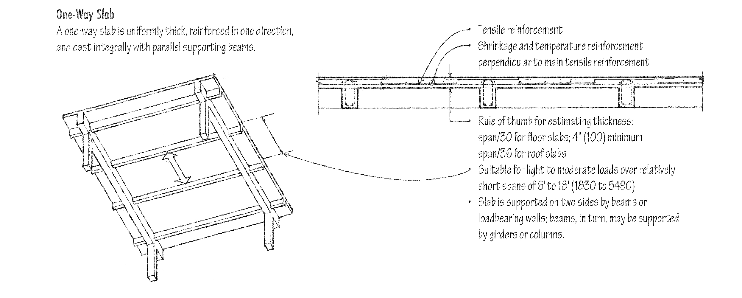
5.1.1 One-way Slab
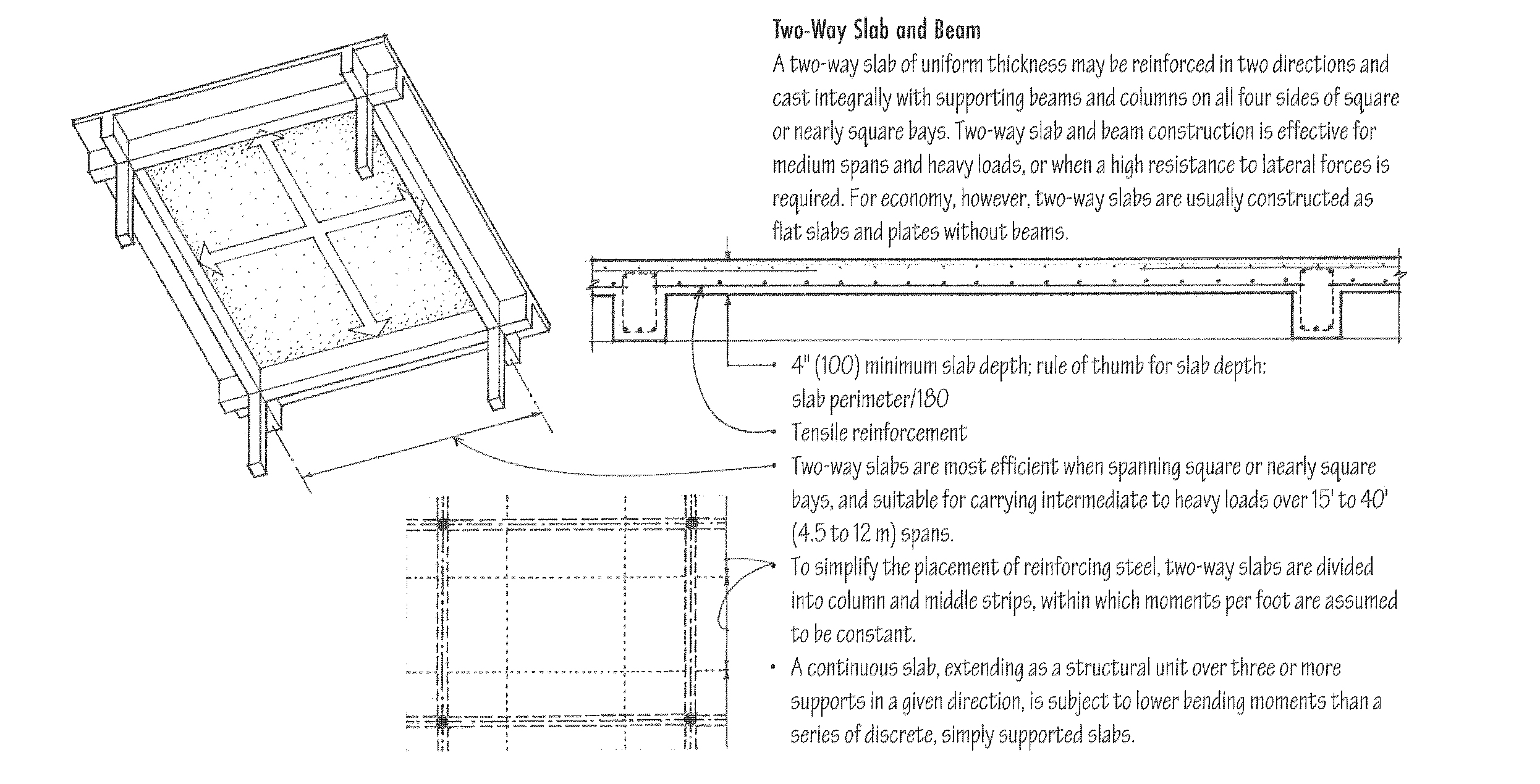
5.1.2 Two-way Slab
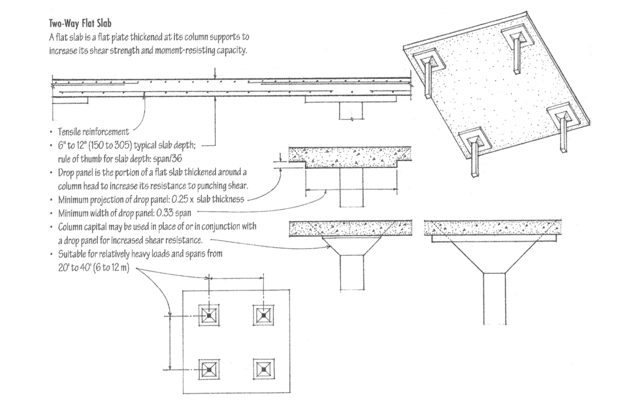
5.1.3 Two-way Flat Slab
5.2 Design Performance Criteria
ALL groups are to use these parameters for the concrete framing of the basement, and the ground floor framing up to the second floor framing slab. We will be using the TWO-WAY FLAT SLAB system for the ground floor and second floor slab ONLY. The rest of your floors above will be structural steel.
CONCRETE COLUMN AND SLAB SCHEDULE
| Dwg. Notation | Type | Size | Location |
|---|---|---|---|
| C1 | Reinforced column | 550mm x 550mm square, or equivalent cross-section area. Include a 900mm x 900mm column capital. | Basement and Ground floor column layout. |
| D1 | Reinforced concrete drop slab | 2950mm x 2950mm, 75mm thick from underside of slab | Suspended Slab locations at ground floor, and second floor framing |
| B1 | Reinforced concrete edge beam | 450mm depth x 225mm thickness | Perimeter of second floor |
| S1 | Reinforced concrete suspended slab structure | 250mm thick | Suspended Slab locations at ground floor, and second floor framing. |
| S2 | Reinforced concrete slab-on-grade | 150mm thick | Slab-on-grade locations at ground floor. |
6.0 Architectural Coordination
6.1 Framed Openings
 Don't forget about duct shafts, rooftop fan units, access hatches, and generally any opening larger than 750mm x 750mm.
6.2 Column Baseplates
Baseplates become an issue when you are dealing with interior finishes, and trying to bury steel members within walls or finish coverings.
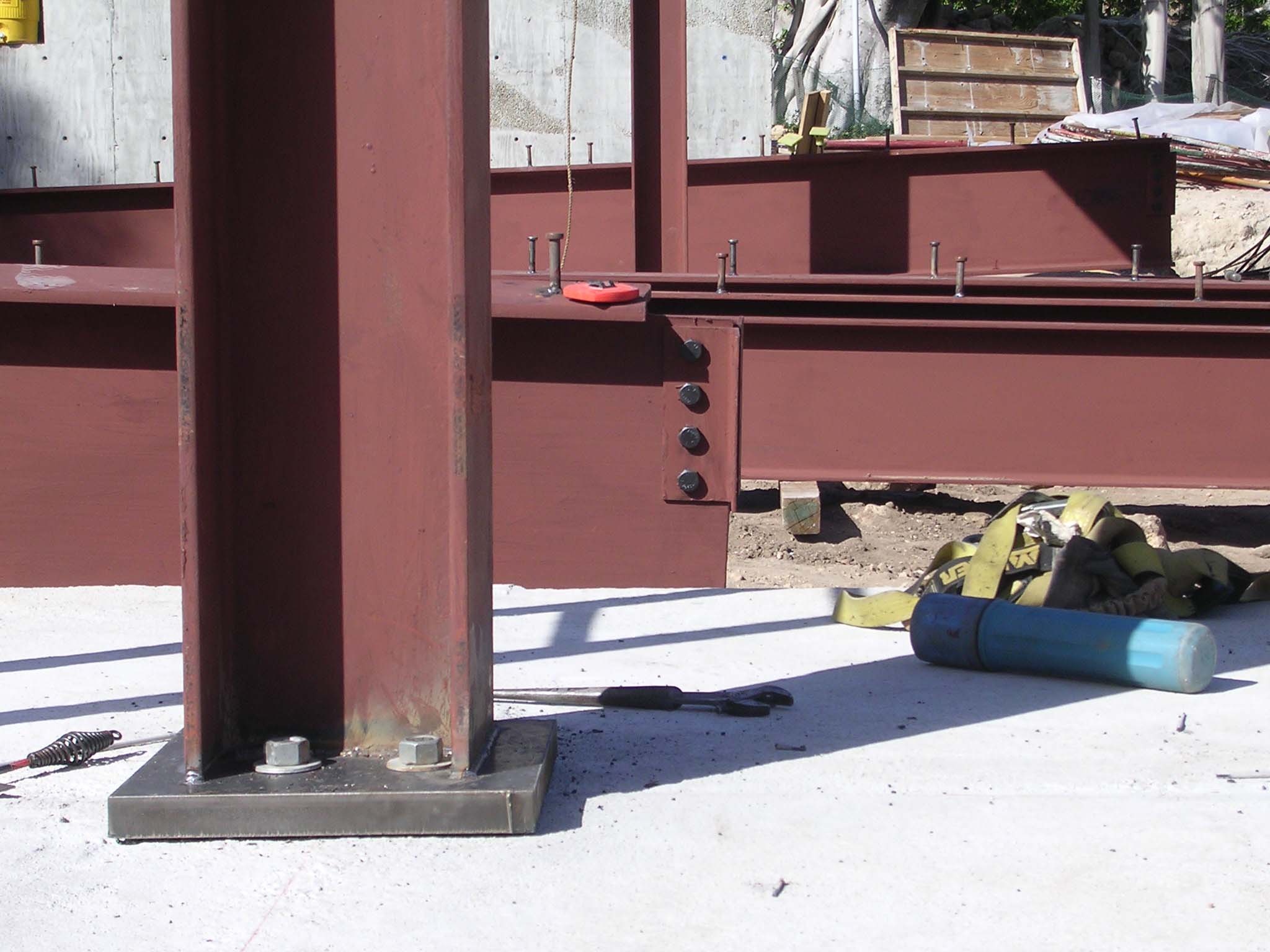
6.3 Plates and Welds
Whether the connections are designed using plates and welds to resist moment (first line drawing), rigid (second line drawing), or shear forces (third drawing), remember these items take up space and require clearances when you place your cladding on your structural frame.
6.4 Lintels
This is especially important when you have openings within shear walls, or load-bearing shear columns. The most common opening: doors!
7.1 Overview
We do not have the knowledge to design commercial foundations, so two 'estimate' foundation schedules have been developed for this stage of the project.
We also have not completed the required soils analysis. So, we need to explore these foundations in both a deep and shallow option.
Each team will develop two foundation options. Team Member 'A' will develop shallow foundations, and Team Member 'B' will develop deep foundation systems.
7.2 Shallow Foundations
Strip footing: continuous concrete slab below a foundation wall width and depth will be determined by soil bearing capacity and local building codes. (Ching, 3.09)
Step footing: strip footings that change levels to accommodate sloping grade or soil conditions. (Ching, 3.17)
Pad Spread footing: thick reinforced concrete slab or pad below a column. (Ching, 3.16)
7.2 Deep Foundations
Grade Beam: reinforced concrete beam at ground level supported by concrete piers and located around the perimeter of a building. (Ching, 3.09)
Mat foundation: heavily reinforced concrete slab under an entire building or part of a building spreading a number of points loads over a larger area. (Ching, 3.09)
Caisson: used where suitable bearing is far below the surface. Deep shafts are drilled, preferably to bedrock and then filled with concrete. A bell shaped enlargement will be made if the bottom of the caisson does not rest on bedrock. (Ching, 3.26)
Piles: slender structural units driven into the ground transmitting loads by frictional surface resistance and / or direct bearing. Piles can be made from wood, steel H’s (wide flange sections), precast concrete, cast in place concrete. (Ching, 3.24)
7.3 Design Performance Criteria
Regardless of the foundation type, remember to include for these items:
SHALLOW FOUNDATION FOOTING SCHEDULE - STUDENT "A"
| Dwg. Notation | Type | Size | Location |
|---|---|---|---|
| F1 | Strip Footing | 900mm wide, 300mm deep | Below all foundation walls. |
| F2 | Pad Footing - Columns | 2500mm x 2500mm, 600mm deep | Below interior columns supporting three (3) storeys and above. |
| F3 | Pad Footing - Columns | 1900mm x 1900mm, 400mm deep | Below interior columns supporting two (2) storeys. |
| F4 | Pad Footing - Columns | 1700mm x 1700mm, 350mm deep | Below interior columns supporting one (1) storeys. |
| F5 | Pad Footing - Columns | 1750mm x 1750mm, 350mm deep | Below typical columns around the perimeter. |
| F6 | Pad Footing - Columns | 1500mm x 1500mm, 350mm deep | Below typical columns around the perimeter that support only one (1) storey. |
| None Required | Piers | Design as follows, to integrate with ground floor concrete structure
|
Typical for all columns. |
| None Required | Foundation Wall | 400mm thickness | Under all perimeter walls. |
DEEP FOUNDATION FOOTING SCHEDULE - STUDENT "B"
| Dwg. Notation | Type | Size | Locations |
|---|---|---|---|
| F1 | Strip Footing | 900mm wide, 300mm deep | Below basement wall perimeter. Exclude the overall building perimeter. |
| F2 | Caisson with a Pier | Design as follows, to integrate with ground floor concrete and upper floor steel structure:
|
Below perimeter columns that are part of the perimeter grade beam system. |
| F3 | Caisson without a Pier | Design as follows, to integrate with ground floor concrete structure:
|
Below all interior columns. |
| F4 | Grade Beam | 1400mm deep, 300mm wide | Around building perimeter to support exterior wall systems (cladding, curtain wall). |
| F5 | Mat Foundation | 600mm deep slab, to overhang foundation walls 125mm | Under elevator cores, stairwells, basement pump rooms. |
| None Required | Foundation Wall | 400mm thickness | To act as basement perimeter walls only. |