
Drawing Property Lines in Site Plans
Drawing Siteplans with arcs:
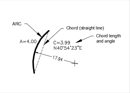
Each arc should have an arc Length, a chord length, a chord bearing angle, and an arc radius.
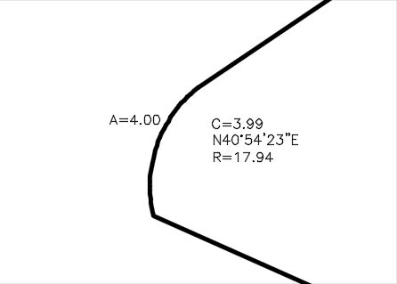
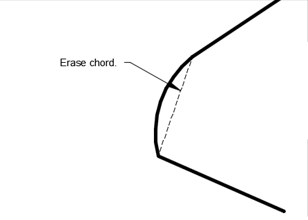
Arcs on property lines are defined by the chord, which is the straight length between the start and end points of the arc.

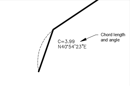
To draw the plan, replace the arcs with lines (use the chord length and the chord bearing angle). You draw the arcs in afterwards.
When planning to draw the property lines, ignore the arc. Imagine you have a straight line (the chord) with a length (the C value) and an angle.
After the property lines (and the chord) are drawn, add the arc. Use the ARC command, Start, End, Radius option.
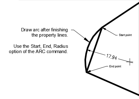
After drawing the arc, use the LIST command or select the arc and look at its properties to see the arc length. Compare it to the (A) value on the survey.
Delete the chord.
Working with Surveyor's angles:
Entering degrees:
Use surveyor's angle units to enter the data.
Instead of a degree symbol, enter the letter 'd', and remove any spaces. You can enter angles in uppercase or lowercase; N is the same as n.
For example:
N 47° 17' 10" E
should be entered as
n47d17'10"E
If you wish to try the sample metric siteplan, download it here.
Steps:
Note: Meters or Millimetres? Since AutoCAD uses mm as the base measurement when scaling in paperspace, we should use mm as well.
@distance<bearing angle
@ means "last point", and < means "using angle of".
So for example the first line on our siteplan would be:
@2030<n34d03'48"E
Note that we entered the length in mm (2030) instead of m (2.03).
Continue entering the data:
@9310<n47d17'10"E
@30000<n42d42'50"W
@10100<S47d17'10"W
Note that this line is not going NE but rather the opposite (SW). To flip the direction of the angle, you change both letters.
@3990<s40d54'23"w
@30150<S47d59'56"E
Adding the arc:
(note: if the arc is drawn wrong, reverse the order of the start and end points (possible), or try entering the radius distance as a negative number (very rare).