Applied Computing and Engineering Sciences (ACES)
 |
School: |
Applied Computing and Engineering Sciences (ACES) |
| Faculty: | Architectural Technology | |
| Course: | ARCH 12356 Architectural Studio 1 |
Architectural Plans - Freehand Graphic Standards for Design Drawings
 |
PAGE CONTENTS |
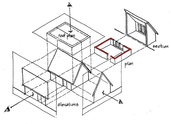
Architectural floor plans are a fundamental component of a set of architectural drawings. These plans incorporate many graphic elements must be completed using standard drawing conventions. The drafting conventions and amount of detail will vary - depending on the scale of the drawing. This module introduced the graphic conventions for architectural floor plans for a variety of scale.

The cutting plane in floor plans is typically about 1500 mm (5'-0") above the floor level. This will ensure that the plan view includes the major vertical elements such as doors, windows, stairs, etc.
Plan view include three major types of elements;
Additionally, architectural floor plans include annotations such as room names, information notes and dimensions. Annotations are typically drawn using a MEDIUM or THIN line weight. Refer to the Lettering Module for information on the appropriate size for annotations.
FREEHAND GRAPHIC STANDARDS FOR DESIGN DRAWINGS
(Note: Graphic standards are different for architectural working drawing
floor plans)
Different scales of drawing result in differing levels of detail for objects and elements in architectural floor plans:
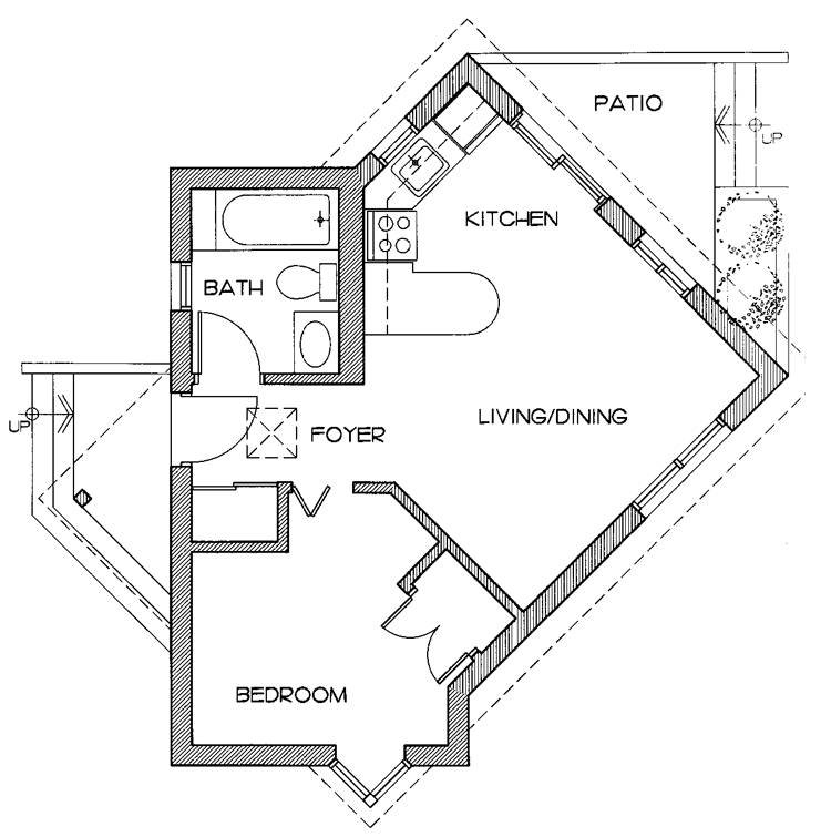
LARGE SCALE ARCHITECTURAL FLOOR PLANS
(Typically 1:50 metric or 1/4"-1'-0" imperial)
Architectural floor plans to these scales are drawn with considerable detail. The hatching of the walls is not mandatory but adds emphasis to the elements that are cut.

MEDIUM SCALE ARCHITECTURAL FLOOR PLANS
(Typically 1:100 metric or 1/8"-1'-0" imperial)
Architectural floor plans to these scales are drawn with some detail, however the graphics of the more complex elements and objects have to be simplified - compare the level of detail used for doors and windows. In this example, the cut walls are emphasised by outlining them with a heavy line work - hatching or solid fill are alternate ways of emphasizing the cut walls.

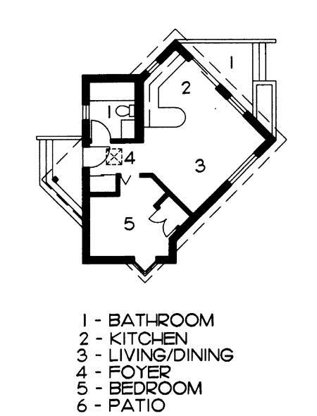
SMALL SCALE ARCHITECTURAL FLOOR PLANS
(Typically 1:200 metric or 1/16"-1'-0" imperial)
Architectural floor plans to these scales are drawn with minimal detail, however the graphics have to be simplified. In this example, the cut walls are emphasised through the use of a solid fill - hatching or heavy outlining are alternate ways of emphasizing the cut walls. Note that it is difficult to include room names in a drawing of this scale - in this example numbers and a legend are used instead.
